A bicycle wheel versus a pneumatic wheel – the load path difference (Part 1 of 2)
- Nimish Prabhukhanolkar
- Jan 24, 2022
- 3 min read
Updated: Jan 23, 2023

The London Eye - https://en.wikipedia.org/wiki/London_Eye
In India, as maybe the rest of the world – a common phenomenon is the local fair. Here in India, when the fair sets up, Ferris wheels, rocking boats, small toy rail cars amongst other things are setup. In India at least – the Ferris wheels mostly used at these fairs look like this image below.

These wheels are engineered in a way – a layman can visualize and understand – strong central trusses radiating outwards, each truss holds a basket in which the audience member sits. There is a weak connection of all baskets along the perimeter of the circle.
Typically – these structures are not more than 15-20 m high. So when London decided to put a 120 m diameter ferris wheel, as the “Millenium Wheel” in the year 2000 at Lambeth, adjoining Thames – the structure would have been expected to have massive central spokes. Consider the 2 numbers – a 15 m diameter ferris wheel looks like the above, how would a 120 m diameter look like? Monstrous trusses!
This is how the Millenium Wheel or “London Eye” actually looks like.

Figure 2 A Side Profile of the London Eye. Src – Wikipedia
How is it – that the members needed for the London Eye – are so small, that they are almost invisible in the above pic?
The first observation from the pic is the following – the spokes are now wire-ropes, and the periphery is substantial. For the fun and fair Ferris wheel – the spokes were substantial while the periphery was just some tie members.
It turns out – when you create a stiff periphery you can then “join” this periphery from all sides to the centre using members that are so weak that they can only carry “tension” – they will fold in compression and you are now – using the “Bicycle wheel” mechanism.

Does this mechanism depend on the wires being pre-tensioned for their stability? I would think not. But pre-stressed wires would allow more uniform participation from all the spokes, while a non-prestressed set of spokes would mean only the lower hemisphere carries the load to the centre.
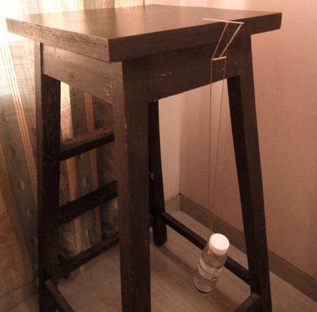
Let me explain a bit more. Consider this wheel with non-pretensioned spokes. As gravity pulls the wheel down, point P moves down, away from the wheel centre, while point A moves down – but towards the centre. So the wire that connects the centre to P will stretch and take loads while the wire that connects A to the centre will be slack. This will be true for the entire upper and lower hemispheres (figure 2).
This leads to the thinking – a wheel in which the top spokes are slack – may have issues like fatigue and deterioration of joints – what if I over-compensate for the tension T that the lower spokes will experience when the wheel is taking its load – by already fitting the spokes so tight – that without any loads, they are all at – say – 1.5*T.
Then, once the load comes in, the lower spokes will become more “tense” and upper spokes will become less “tense” but none will be at 0 tension – giving me a more equitable config.
Thus, the vertical load paths are taken care of – in bicycle action.
But what about lateral load paths? For the layperson – this means, the above wheel is still not stable. It will just crumple laterally, like the illustration shown.

The wheel has to be made laterally stable too – I can tell you my guess of how the London eye is laterally stable.
There are 2 lateral “holds” or “grooves” below that prevent the wheel from coming out of its vertical plane. These seem to be framed structures independent from the main frame, and do not prevent the circular rotation of the wheel – but prevent it from tilting out of plane. See image below, for a better understanding.

There are no such holds – in an actual bicycle wheel though – how is that then laterally stable? Another sneaky mechanism – also helped by some physics action. To preserve brevity – I leave this to be figured out in comments.
If the bicycle mechanism is the more optimal one, why does your neighbourhood ferris-wheel owner not use it? Perhaps the reasons could be –
a) A much higher design expertise needed for decided the wire rope “spoke” tensions, their terminations, pre-stressing.
b) Lack of modularity – this cannot be easily dismantled.
But if any reader of mine – has a huge 50m plus ferris wheel on his pipeline – do take inspiration from the bicycle mechanism and the London Eye!
Link to pdf article: https://1drv.ms/b/s!Atiw1Agqj0D4ovFLfH6uczMmL9DCaA?e=h9Ke29
To be continued … Part II (Pneumatic Tyres Load Path)
Comments